Custom designed Searchlight Signals using printed circuit boards that resemble signal masts to serve as placeholders until trackside signals get installed.
BACKGROUND
Here is an example of a GRS signal on the Denver & Rio Grande Western, the railroad I model. Note black signal targets and silver mast.
It is going to be a long time before my layout has scenery and trackside signals so I decided to make printed circuit board signals to serve as stand-ins. The circuit boards will be sized to match the prototype signals as well as possible..
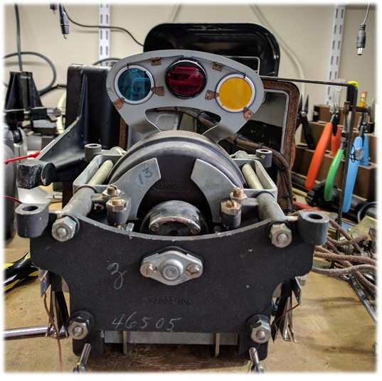
The internals of a GRS Searchlight. The arm with the three colored rondels (light filters) is moved by a very efficient electrically-driven mechanism so that the appropriate filter is placed in the light beam. The arm is centered by gravity to ensure a Red appearance if the drive circuit or mechanism were to fail.
Notice the colors of the rondels, particularly the bluish tint of the green one. These colors were specifically chosen to make the different appearances as distinct as possible. Finding an LED that matches these colors well was a goal for the project.
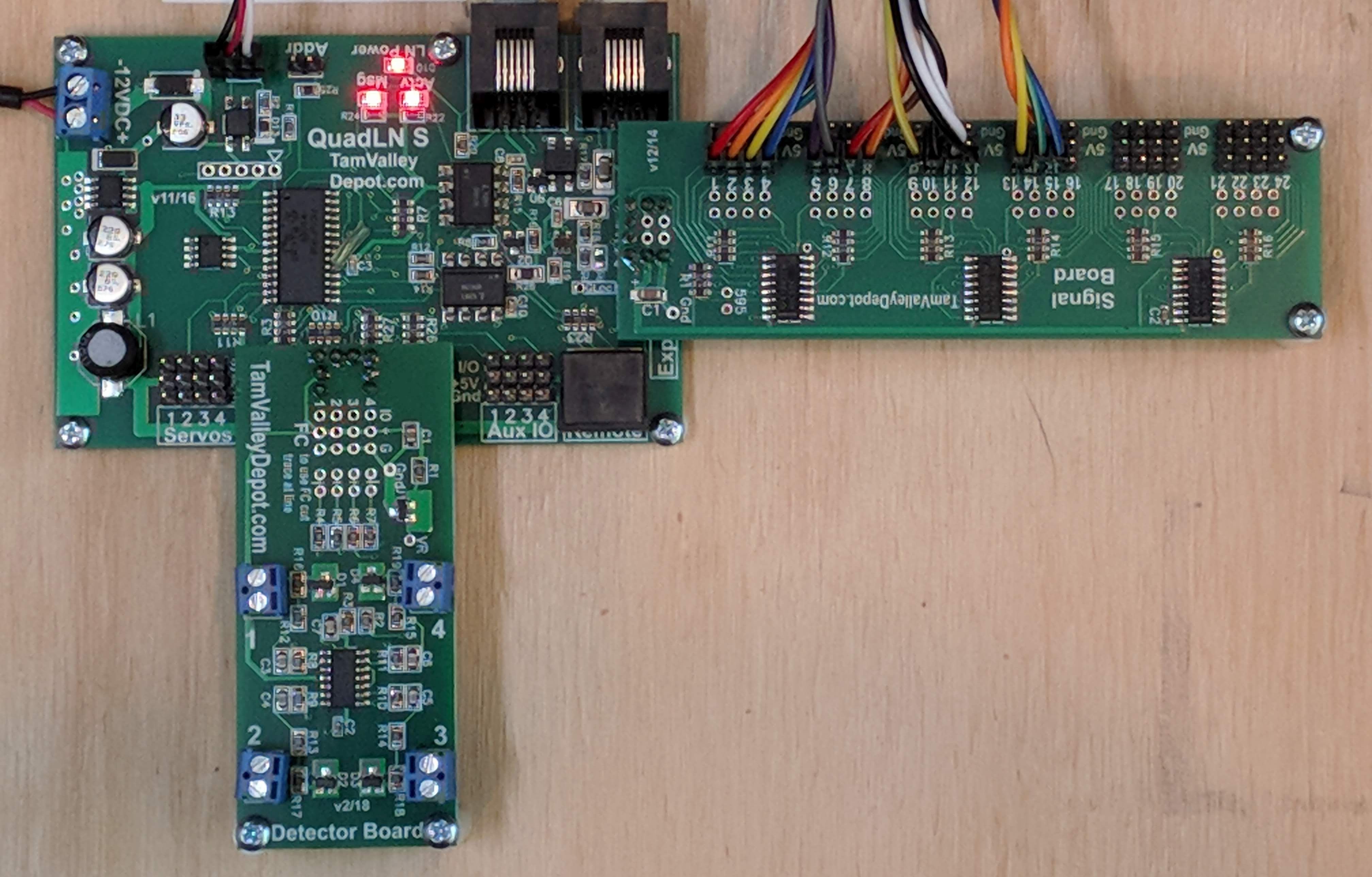
Each OS on my layout is controlled by a QuadLN_S with Signal and Detector Boards. This configuration handles 8 servos, 4 block detectors and 24 signal LEDs. Each QuadLN_S is linked with JMRI via Loconet.
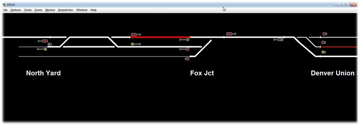
Working JMRI panel showing the signals around Fox Jct on my layout. This panel drives the QuadLN_S Signal Boards mounted at each OS around the layout. Everything is in place for trackside signaling, except for the trackside signals! Time to design and build the circuit boards.
LED and Circuit Board
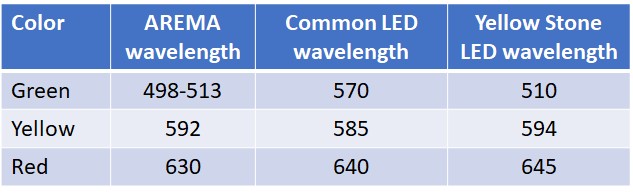
Here is a comparison of the colors produced by a common RYG LED to those produced by the Yellowstone LED I chose for this project. Note the close match between the Yellow Stone LED and the AREMA standard color. The LED part number is BL-HUBG4KC36T-TRB
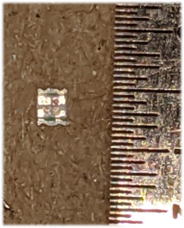
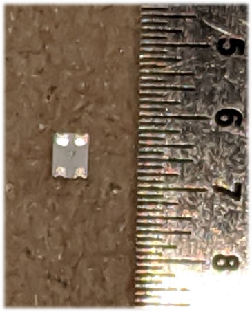
Here is the Yellow Stone LED. The size is 0605, which means .060″ x .050″. Notice the 3 individual LEDs, one for each color.
The Red, Yellow, Green and Common LED connection pads are visible in this closeup.
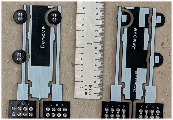
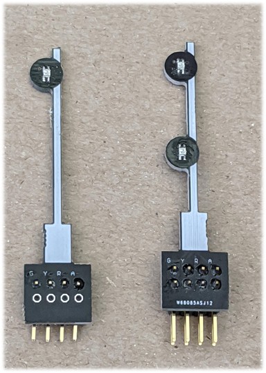
Single and dual head versions of the circuit board. I used standard dual inline headers for the signal wiring connections. Black solder mask makes the signal targets look good and white silkscreen simulates the mechanism, silver mast, base.
Front view with the LEDs mounted and headers installed.
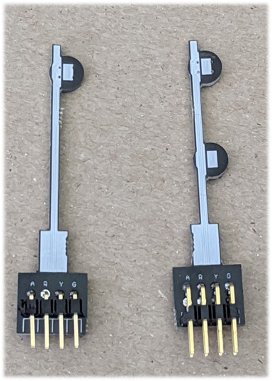
Rear view showing the single and dual row right angle headers that will connect to the signal drive cables.
Results
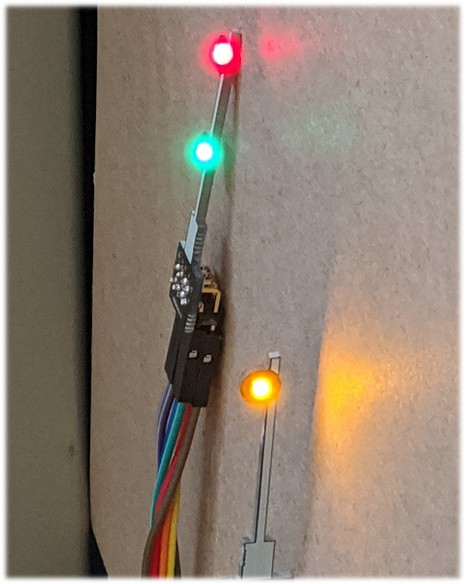
The illuminated LEDs show how closely this part matches the prototype signal.
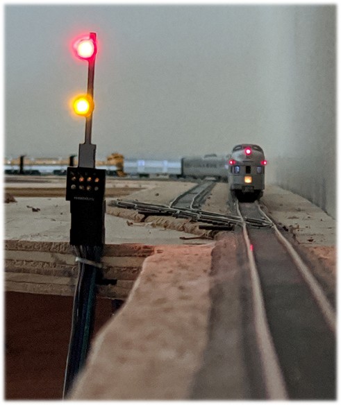
Dual head signal at Fox Jct. This will do nicely until scenery and trackside signals are in.
Short video showing the QuadLN_S Signal board creating the classic searchlight signal red flash in the middle of the transition from yellow to green. This flash is a hallmark of searchlight signals and results from the mechanism design shown above – when moving between Green and Yellow, the Red rondel is briefly placed in front of the lamp. Getting this effect right was a major goal when I developed the QuadLN_S signaling software. The video quality is poor but the effect still comes through. Looks better in person!
If you look really closely you may notice a bit of “wobble” in the Green appearance immediately following the transition. I first saw this on prototype signals and later on my own GRS SA searchlight mechanism. The wobble results from a small amount of bounce off the stop when the mechanism reaches the end of travel. Naturally when I developed the QuadLN_S signal software I had to implement the wobble too!