Signal Connector Interface Boards using Ethernet Cables
Signal RJ45 Conversion Kit
$10.95 INTRO $6.95
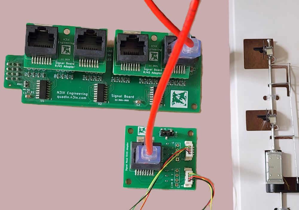
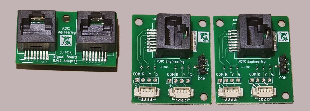
This kit lets you connect the QuadLN_S Signal Board to your signal heads using ethernet cables instead of traditional servo cables. The kit consists of one Signal Board RJ45 Adapter plus two RJ45 Signal Wiring Boards. Standard ethernet cables connect the Signal Board RJ45 Adapter to the RJ45 Signal Wiring Boards. There is no special requirement on the cable – any straight-through 8P8C cable terminated in RJ45 connectors should work fine.
The Signal Board RJ45 Adapter plugs directly into the QuadLN_S Signal Board and routes 12 LED outputs (half of the total LED outputs) to two RJ45 connectors.
Each RJ45 Signal Wiring Board is located near the signal masts and provides access to 6 LED outputs, enough to handle two signal heads. There are solder pads for the signal wires plus JST1.25-type connectors to support Atlas® and other signals with pre-installed connectors. An onboard jumper allows selection of either Common Anode (newer Atlas/BLMA) or Common Cathode (older Atlas) signal wiring. Built-in current limiting resistors are provided for each LED.
Signal RJ45 Conversion Kit is supplied as a set of 3 boards: one Signal Board RJ45 Adapter and two RJ45 Signal Wiring boards. The QuadLN_S Signal Board and ethernet cables are not included. One kit supports 12 LED outputs from QuadLN_S Signal Board: to convert all 24 LED outputs order 2 kits.
See the Signal Cables with Connectors item below if you wish to add connectors to signals that don’t have JST1.25 connectors pre-installed.
The Signal RJ45 Conversion Instruction Sheet is available on the Downloads page.
Signal Connector Interface Boards using Servo Cables
Signal Connector Interface Board – Set of 8 Boards
$19.95
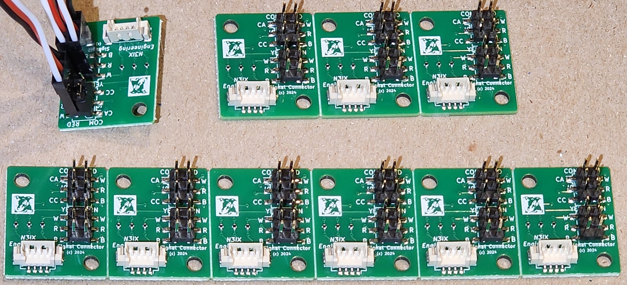
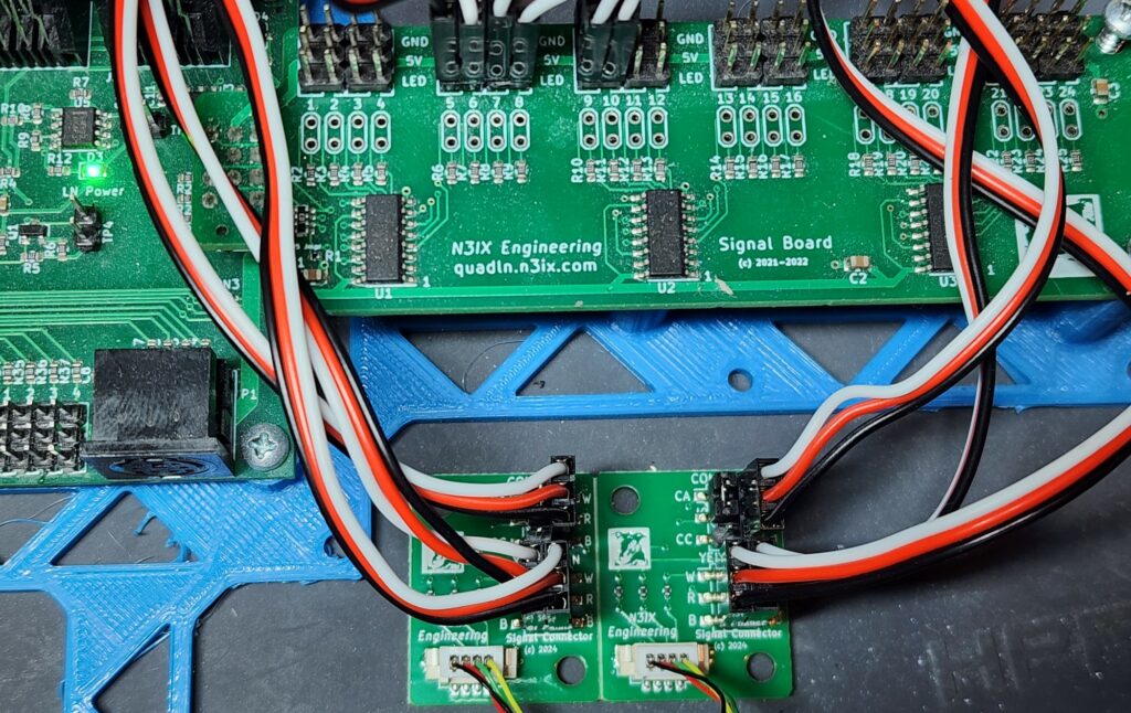
The Signal Connector Interface allows Atlas® and other signals that use JST1.25-type connectors to be easily driven from a QuadLN_S Signal Board. One Signal Connector Interface Board is required per signal head. Connects to the QuadLN_S Signal Board using separate 3-wire servo cables for the Red, Yellow and Green LEDs to allow easy routing to any desired Signal Board outputs. An onboard jumper is provided to select either Common Anode (newer Atlas/BLMA) or Common Cathode (older Atlas) signal wiring. Built-in current limiting resistors are provided for each LED. Each Signal Connector Interface Board includes three 12″ cables that plug into the Signal Board – increase the distance by adding standard servo extension cables.
Signal Connector Interface Boards are supplied as a set of 8 boards: one panel of 6 boards and one panel of 2 boards. The panels can be snapped apart as desired into individual boards for one head signal masts, two board sets for dual head masts, etc. The set of 8 boards can support 8 signal heads using all 24 outputs on one QuadLN_S Signal Board.
To use these boards with signals that don’t have JST1.25 connectors pre-installed, see the Signal Cables with Connectors item below.
The Signal Connector Interface Board Instruction Sheet is available on the Downloads page.
Signal Cables with Connectors – Set of 8
$3.50
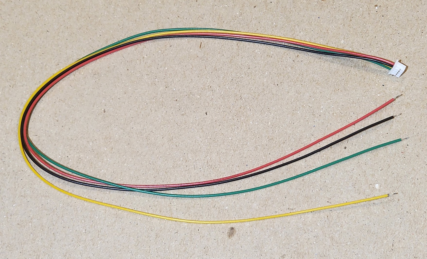
8″ or longer cable with JST1.25-type connector. Use these cables to add connectors to other brands of signals so they can plug into the Signal Connector Interface Board. 8 cables per set.
Note: These cables come preassembled and the wire color order is typically Green-Yellow-Black-Red which is different from the Atlas cables. The connector pinout order on the Signal Connector Interface Board is Common, Red, Green, Yellow (matching Atlas signal mast cables). The important point is that Common is on the left and that means that the Green wire will be the Common. Please wire carefully to your signal heads. You can connect the remaining 3 wires to the LEDs in the signal head as you like, for example Red wire to the Red LED, Yellow wire to the Yellow LED and Black wire to the Green LED. As long as the Common is wired correctly, no matter how the other wires end up connected to LEDs you can always adjust the LED pin assignments in the Signal Aspect table as needed to match.
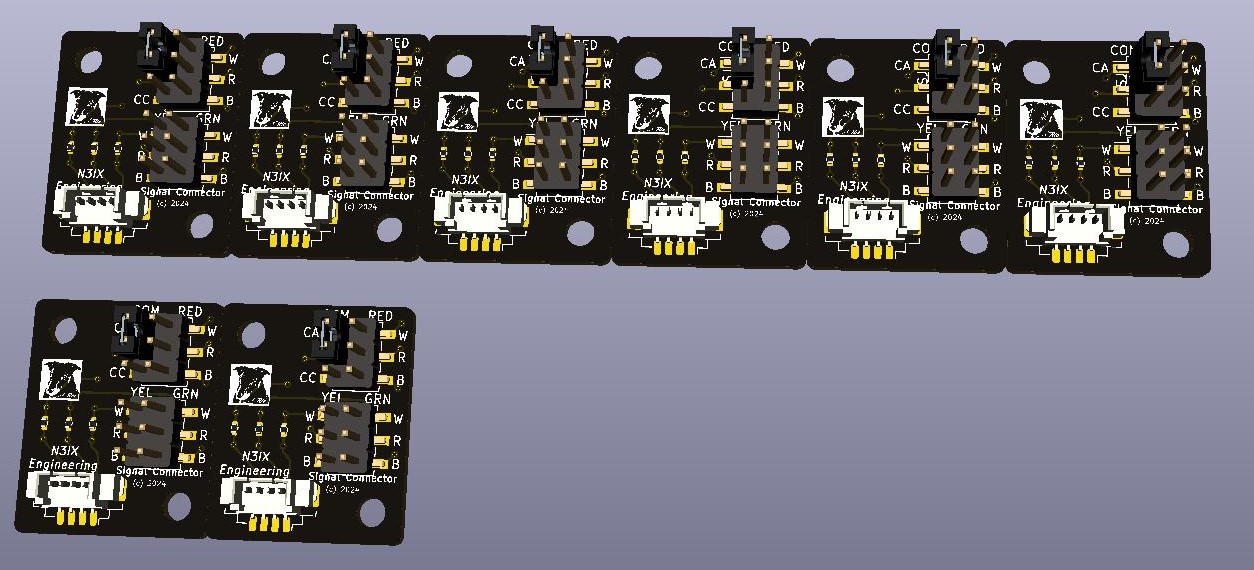
Signal Connector Interface Board – Set of 8 Boards without servo cables
$9.95
The same Signal Connector Interface Board set as above but without any board-to-board servo cables. You provide your own cables to connect the headers on each board to the headers on the Signal Board.
Signal Wiring Breakout Boards
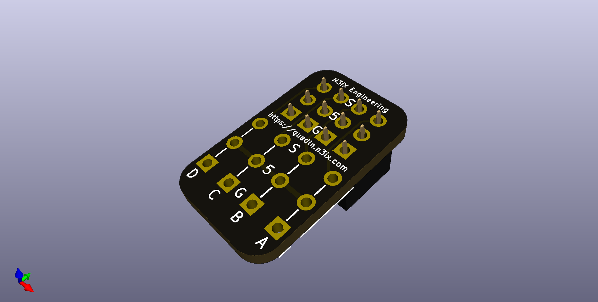
Remote Signal Wiring Breakout Board with Solder Pads
$3.50
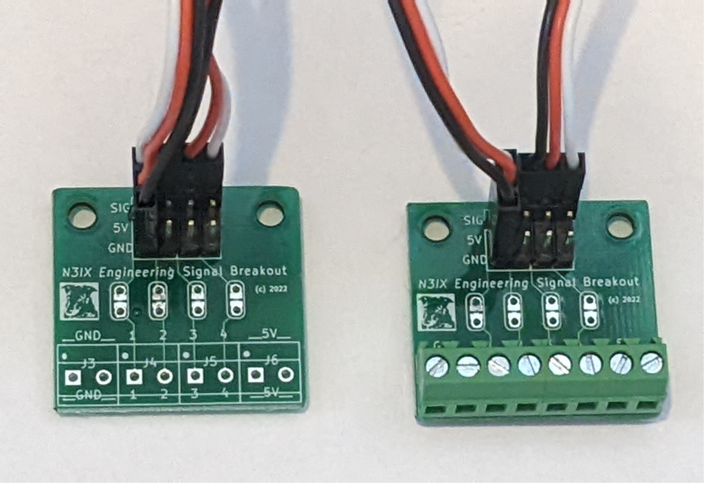
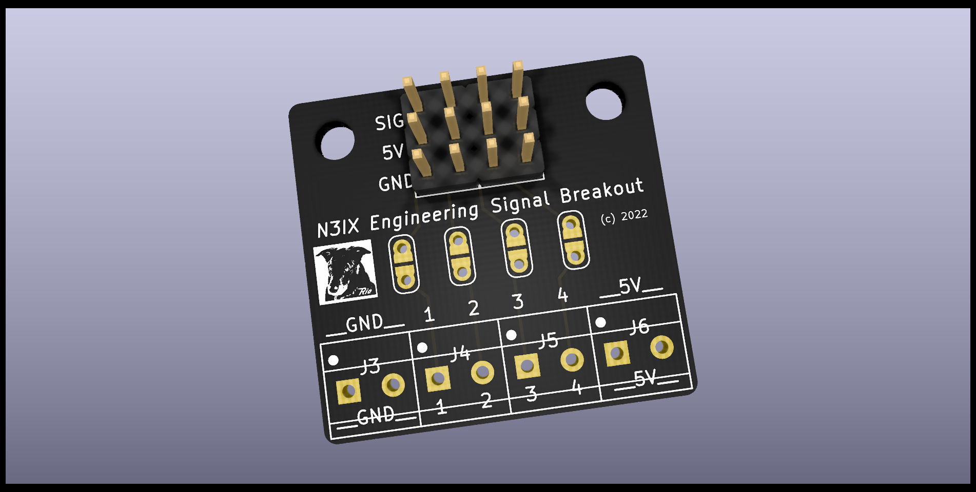
Connects to the Signal Board remotely using 3-wire servo cables. Has solder pads for up to 4 LED outputs along with +5V and Ground. Trace cuts with solder pads make it easy to install additional series resistors when needed. Comes with two 12″ cables that plug into the Signal Board. Increase the distance by adding standard servo extension cables.
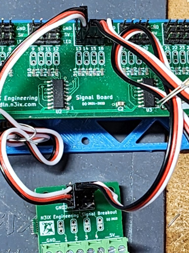
Remote Signal Wiring Breakout Board with Screw Terminals

$4.50
Connects to the Signal Board remotely using 3-wire servo cables. Has screw terminals for up to 4 LED outputs along with +5V and Ground. Trace cuts with solder pads make it easy to install additional series resistors when needed. Comes with two 12″ cables that plug into the Signal Board. Increase the distance by adding standard servo extension cables.
Plug-in Signal Wiring Board with Solder Pads
$1.75
Provides solder pads for wiring your LEDs to the Signal Board. Has solder pads for 4 LED outputs along with +5V and Ground. Plugs directly into the Signal Board. Can also be plugged into any QuadLN_S IO Port for direct wiring of IO devices.
Signal Board Tester

Half Signal Board Tester
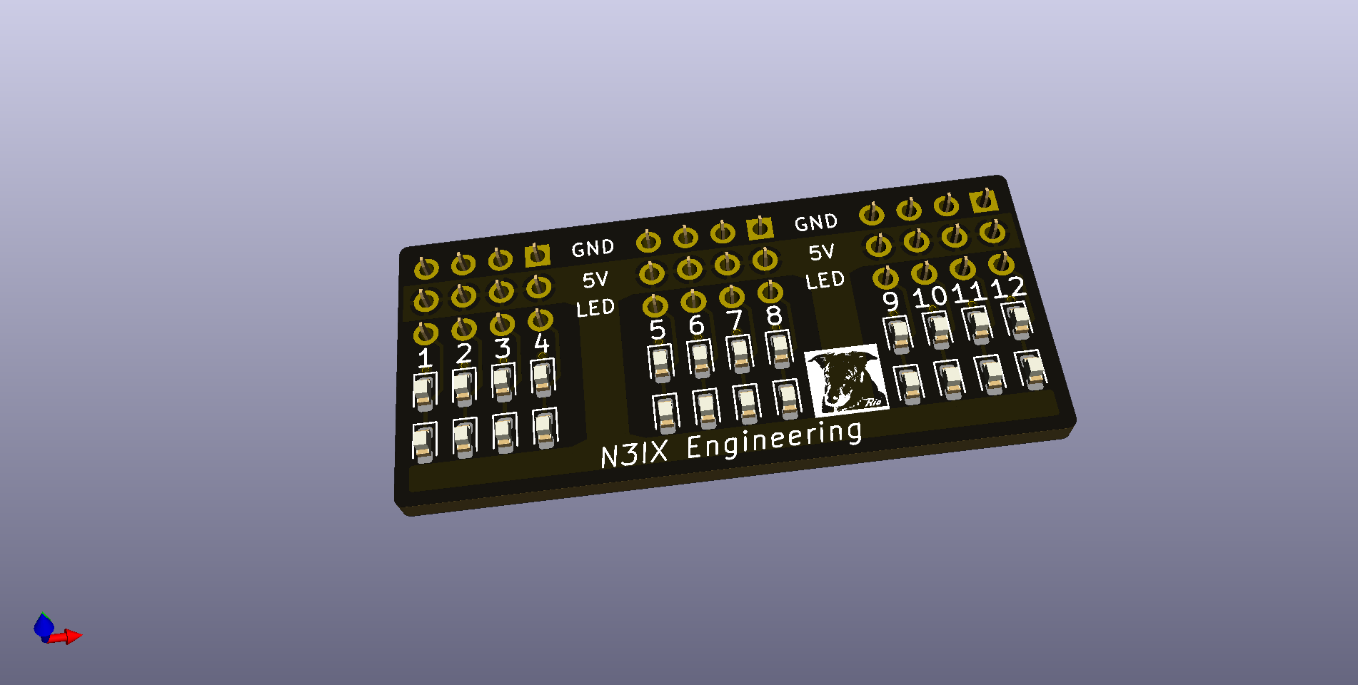
$6.95
Tests 12 Signal Board outputs. Two LEDs per output to test both high and low output drive. Use 2 boards to test all 24 outputs simultaneously.
Insert the ADDR jumper and the QuadLN_S will continuously toggle each output. (If connected to LocoNet, be sure to remove the ADDR jumper when done testing to prevent inadvertent changes to the Turnout Start Address)